Key figures required for injection molding machine selection
- SANKO GOSEI
- Nov 12, 2024
- 4 min read
Injection molding machines need to be selected according to the product molding method and required specifications.
In this issue, we introduce each of the eight factors necessary for the selection of a molding machine.
(1) Clamping force
The clamping force is the maximum value of the force to close the mold and is generally expressed in (ton).

(2) Projected area of moulded products
The projected area is the area when projected onto a plane perpendicular to the direction of movement of the clamping device. If the direction of the dashed line in the product in the diagram below is the direction of movement of the clamping device, the projected area is as follows

(3) Required clamping force of forming machine - clamping force [ton], forming area [cm2].
The maximum clamping force and the maximum projected area that can be formed. The following formula is used as a guide for converting the required clamping force to the action of the material pressure that tries to open the mold.
F = a・Pm・(n・A+B)/100
F: Required clamping force of the molding machine [tf] a: Safety factor (generally 1.1 to 1.2) [-] Pm: Average material pressure in the mold [kgf/cm2].
n: Number of molded parts A: Projected area per molded part [cm2] B: Projected area of runners, etc. [cm2].
![成形機の必要型締力[tf]](https://static.wixstatic.com/media/217ce4_e1f91ac9353945b2839f9e9b78faa40f~mv2.png/v1/fill/w_537,h_430,al_c,q_85,enc_avif,quality_auto/217ce4_e1f91ac9353945b2839f9e9b78faa40f~mv2.png)
*1: Actual injection pressure P does not match Pm due to pressure drop during the process of filling the mold.
*2: The average in-mold material pressure Pm varies according to the type of material, and also according to the dimensional accuracy of the design of the molded product and the level of quality requirements (such as the size of sink marks).

*3: Other points to consider when selecting an injection molding machine include the volume of the molded product, the size and structure of the mold, and the mold opening and closing stroke.
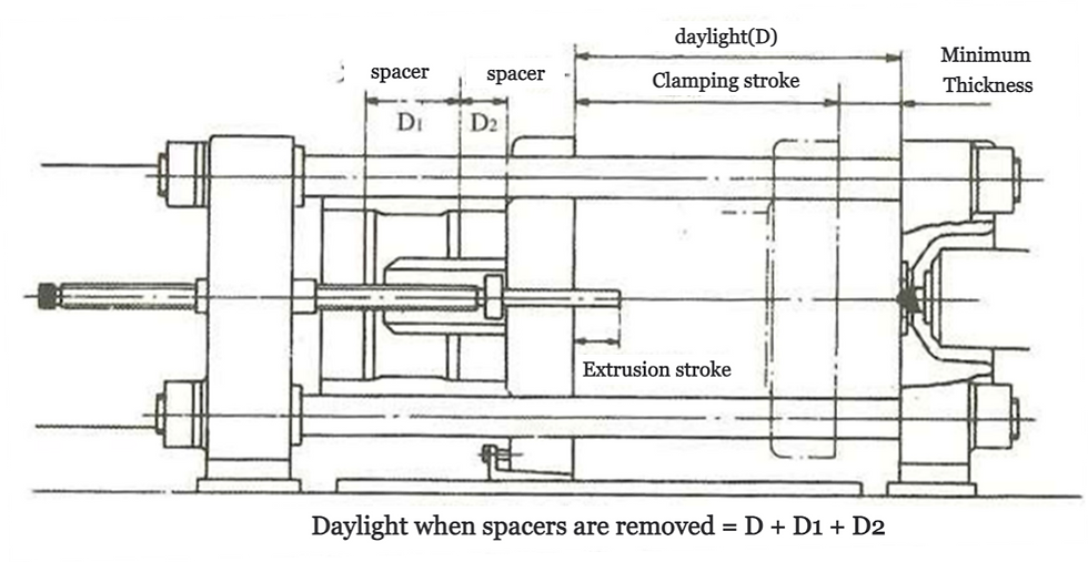
(4) Max. mould opening distance (daylight), max. and min. thickness, clamping stroke

Dimensions related to mould mounting (direct pressure type)

Mould mounting dimensions (toggle type)

Required mould opening and closing strokes and die plate spacing for 2-plate moulds (for direct sprue)

Required mould opening and closing strokes and die plate spacing for 3-plate moulds (for pin-point sprues)
(5) Injection volume (injection capacity)
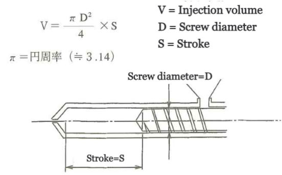
Injection volume at maximum stroke. It is also called theoretical injection volume and is calculated by the following formula. It is expressed in cubic centimetres (cm3).

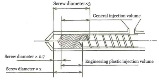
Theoretically, the stroke is calculated using the above formula, but in practice, a value of 0.7 to 3 times the screw diameter is generally considered to be calculated as the stroke. For engineering plastics, the stroke is calculated as 0.7 to 2 times the screw diameter.
The reason why the minimum stroke is set at 0.7 times the screw diameter is that the limit at which hydraulic pressure and other components can respond to the moulding machine control programme is generally said to be 0.7 times the screw diameter.
The reason why the maximum stroke of engineering plastics is twice the screw diameter is said to be because the moulding temperature of the material is relatively high (high resin sound) and requires a large amount of heat.
Silver streaks, short shots, etc. are likely to occur when moulding with an injection volume of more than twice the screw.

An example of an injection volume calculation for engineering plastics is given below.
Injection volume of screw diameter - φ4
Cross-sectional area of screw diameter = π x 4^2/4 = 12.56 cm2
Minimum stroke = 4 x 0.7 = 2.8
Maximum stroke = 4 x 2 = 8
In injection volume
Minimum injection volume = 12.56 cm2 × 2.8 = 35.16
Maximum injection volume = 12.56 cm2 × 8 = 100.48
and the final injection volume of this screw is between 35.16 and 100.48.
(6) Injection pressure.
Injection pressure is the maximum pressure (kgf/cm2) generated at the screw tip.
The pressure required for moulding varies greatly depending on the shape of the product and the structure of the mould, but commodity resins require a low pressure and engineering plastics require a relatively high pressure.
Engineering plastics require a relatively high pressure. The following is a rough guide to the required pressure.
General-purpose plastics: 1,200 kgf/cm2 or more.
General-purpose engineering plastics - 1,500 kgf/cm2 or more
Super-emplers - 2,000 kgf/cm2 or more.
As a general trend, the higher the load deflection temperature (heat deformation temperature) and molding temperature of the molding material
The higher the load deflection temperature (heat deformation temperature) and molding temperature of the molding material, the higher the required pressure.
The above values are the set pressure applied to the rear of the screw. However, the pressure loss in the middle part of the screw is large, so the actual nozzle pressure is higher.
The actual resin pressure at the nozzle is said to be 50-60% of these values.
To be precise, a pressure sensor should be installed and checked.
(7) Injection rate.
Indicates the rate of injection of molding material from the nozzle, expressed as the maximum volume that flows out in unit time.
The diameter of the screw is D (cm), the injection velocity is v (cm/sec), the injection volume is V (cm3) and the injection time is t (sec),
If the diameter of the injection cylinder is D0 (cm) and the hydraulic oil flow rate is Qo (cm3/sec), the injection rate Q (cm3/sec) is
expressed by the following equation
Q=(πD2/4)・v Q=V/t, or Q=Q0・D2/Do2
(8) Plasticising capacity (kg/hr)
Indicates how much moulding material the heating cylinder plasticises per hour. In practice, plasticising performance is related to injection volume, back pressure, screw speed, etc., and may affect material temperature uniformity and metering accuracy, especially in precision high-cycle moulding.


Comments