

Reduction in processing time through machining improvements at the ejector block joint section
- SANKO GOSEI
- Dec 8, 2025
- 4 min read
Introduction
Ejector blocks are critical components for removing molded parts from the mold. Due to the recent trend towards higher cycle rates and thinner-walled products, the number used per mold for large molded parts is increasing, ranging from 40 to 120 units.

This tendency is particularly pronounced in interior molded parts such as automotive components, which feature numerous reinforcing ribs on their backsides.
Consequently, machining hours for ejector blocks have also increased significantly. To achieve cost reduction and lead time shortening, a review of machining methods is essential. This paper details the background, challenges, improvement measures, and results of the ‘Ejector Block Joint Machining Method Improvement’ project by the Machining Technology Group at S-Bans Co., Ltd. It also considers the potential for application to other industries.
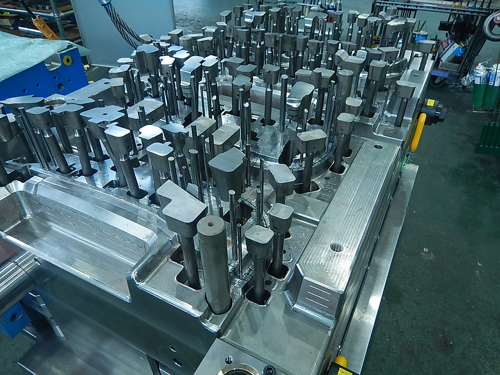
What is an Ejector Block?
It is a block used to eject the product from the mold.
In the case of a tilting block, even if the product shape has undercuts,
the undercuts can be processed by ejecting the entire block.


Background and Challenges
1. Joint Machining as a Bottleneck
While unmanned machining (NC machining) is typically the mainstream method for processing ejector blocks, the machining of the joint sections (screw and knock pin holes) required high precision, necessitating reliance on manned machining.
There are two types of joints:
Screw-in joint (in-house standard)

・Tapping operations predominate, making defects such as stripping prone to occur
・Re-manufacturing is required when machining defects occur
・Operations are manned, with unmanned operation during nights and holidays impossible
Knock pin joint (customer specification)

・This is a load-bearing section where fitting accuracy is critically important
・Previously required combined machining of blocks and pins
・Process complexity increased, reducing equipment utilisation rates
Thus, all joint methods faced challenges including increased labour time, higher costs, and reduced machine utilisation rates.
Improvement Objectives and Policy
Target Values (Cost Reduction)
Screw-in Joint:
Machining cost: Approximately ¥6.075 million annually
Target: 60% reduction (¥3.6 million/year)
Knock Pin Joint:
Machining cost: Approximately ¥1.879 million annually
Target: 40% reduction (¥751,000/year)
Improvement Strategy
Screw-in Joints
Achieve full automation (unmanned machining)
Replace tapping with new tools (thread milling cutters)
Implement continuous machining using CAM data
Knock-in Joints
Switch to single-piece machining for blocks and pins
Eliminate simultaneous machining by utilising NC multi-tasking lathes and 5-axis machining centres
Standardise and unify tip diameters
Specific Improvement Measures
1. Improvement of Screw-in Joints
Conventional tapping required manual cutting oil application, frequently causing thread stripping.
Switching to thread milling enabled automatic water-soluble cutting fluid supply and improved chip evacuation. Furthermore, batch continuous machining via CAM data was achieved, realising fully unmanned processing.

The challenge involved a discrepancy between tool diameter correction values and actual machining accuracy, necessitating numerous test runs to determine optimal values. Furthermore, the precision of pilot hole machining proved problematic, leading to a switch from drilling to milling operations.
2. Improvement of Knock Pin Joint
Block Pin Side
To accommodate variations in material diameter (maximum 0.06mm), the tip was uniformly machined down by -0.1mm, thereby clarifying the mating reference.

NC multi-tasking lathe enables full automation from tip face machining through seat machining to hole machining.
Block side
Eliminates the need for physical machining based on actual pins as previously required.
Fully automated machining including pin holes is achieved on a 3-axis machining centre without the need for setup changes.

Significantly reduced machining time and simplified processes.
Challenges during improvement and their resolution
・Thread mill fitting adjustment
A phenomenon where fitting becomes too tight due to discrepancies between actual tool diameter and theoretical values. Compensated by identifying correction values through testing on each machine.
・Knock pin fitting accuracy
As this is a load-bearing area, adjustment for fitting being ‘too tight/too loose’ is required. Repeated fine adjustments at the tip location identified the optimum position.
・Deployment to 3-axis machining centres
Machining accuracy acceptable on 5-axis machines caused defects on 3-axis MCs due to table rotation error. Addressed by revising the level verification method and setting tolerance values.

Results and Effects
◆ Screw-in Joint
Annual savings: ¥4,212,000
Utilisation of night-time operation through unmanned machining
Significant reduction in remanufacturing risk
Reduction in machine downtime (improved utilisation rate during nights and holidays)
◆ Knock Pin Joint
Annual savings: ¥1,005,000
Increased equipment utilisation through elimination of simultaneous machining
Enables production of individual required components
Machining time: 25 minutes → 11 minutes per piece (approx. 56% reduction)
Future Prospects
This improvement is not limited to ejector blocks; future expansion is anticipated into the following areas:
Application to other equipment (3-axis machining centres, multi-tasking lathes, etc.)
Application to machining mating holes for mold bodies, protruding plates, mounting plates, etc.
Feedback into standardised in-house machining flows and company-wide implementation
Summary
This improvement initiative achieved ‘unmanned operation for screw-in joints’ and ‘single-piece machining for knock pins’, resulting in labour savings equivalent to approximately ¥5.2 million per annum. These outcomes extend beyond mere cost reduction, yielding multifaceted benefits including enhanced machining stability, shortened lead times, reduced troubleshooting, and improved equipment utilisation rates.
This case demonstrates that even seemingly simple components like ejector blocks can yield significant improvements through process re-evaluation. We anticipate this initiative will serve as a model for future mold design and machining operations.


Comments